
 Click to zoomTap to zoom
Ultracapacitors · Bank assembly
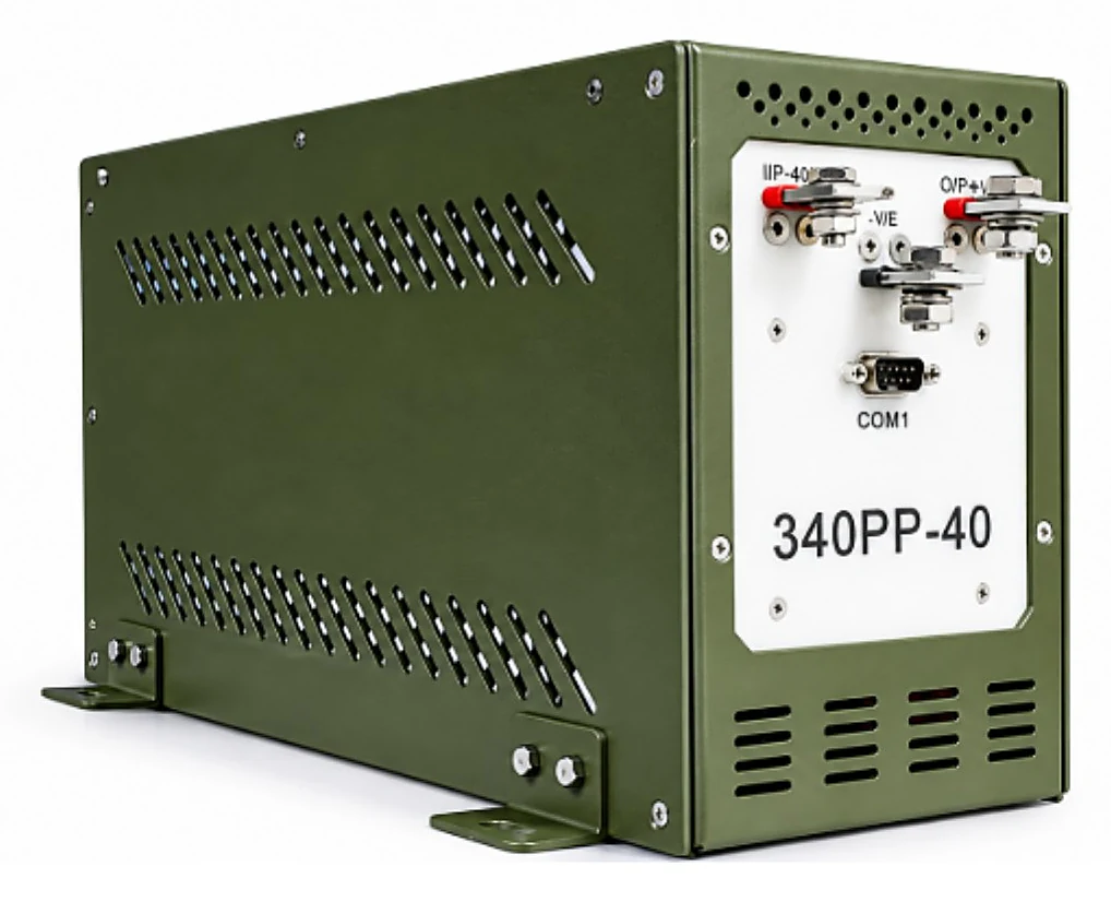
Faradigm 340PP-40 Ultra-Capacitor Bank Assembly
340 V DC · 0.71 F · CAN health status via DB9
- Nominal voltage
- 340 V DC (380 V DC max)
- Capacitance
- 0.71 F
- Peak discharge
- 80 A for approx. 250 msec
- Charging
- 2.5 A, full charge in 100 sec
- Weight
- 8 kg or less
- Dimensions
- 410 × 164 × 220 mm (max)
An ultra-capacitor bank assembly for 340 VDC systems (380 VDC maximum), connected at the output of a DC-DC converter. It keeps power available to servo motor control through the motor drive, delivering 3.5 A for 0.3 sec and 7 A for 0.45 sec, with a peak discharge of 80 A for approx. 250 msec.
← Back to all ultracapacitorsPower availability for servo motor control.
Servo drive support
3.5 A for 0.3 sec and 7 A for 0.45 sec, with a peak discharge of 80 A for approx. 250 msec.
Regenerative protection
Protection against up to 680 VDC during motor deceleration is built in.
Health status on CAN
Available charge, bus voltage, charging current and temperature fault, reported on CAN protocol via a DB9 connector.
Qualified for ground vehicles
Built for applications that need JSS 55555 and MIL-STD-461G qualification.
- 100 sec
- fully discharged to fully charged
- 80 A
- peak discharge
- ≤ 8 kg
- weight
- -30°C to +60°C
- operating temperature
Specifications
Full technical data.
| Model Number | 340PP-40 |
|---|---|
| Nominal Voltage | 340V DC |
| Max Operating Voltage | 380V DC |
| Regenerative Voltage | 680V DC (during motor deceleration, for a few milliseconds, ~150 ms); protection against regenerative voltage incorporated |
| Capacitance | 0.71F |
|---|---|
| Equivalent Series Resistance | 1200 mΩ |
| Allowable Voltage Drop | 10V DC (from 340V DC during discharge at specified nominal discharge current) |
| Discharge Current (Nominal) | 3.5A for 0.3 sec and 7A for 0.45 sec |
|---|---|
| Peak Discharge Current | 80A for approx. 250 msec |
| Charging Current | 2.5A; fully discharged to fully charged state in 100 sec |
|---|---|
| Reverse Current Protection | Stud diode in charging circuit against reverse flow of current from input terminal |
| Short Circuit / Over Current | Beyond 120A; 25A, 500V DC cartridge fuse |
|---|---|
| Over Temperature | Provided |
| Control Voltage (Internal Circuitry) | External 28V DC, 1A ± 15%, isolated power supply via DB9 connector |
|---|---|
| Health Status | Available charge, bus voltage, charging current, temperature fault, etc. on CAN protocol via DB9 connector |
| Terminals | I/P +VE stud, O/P +VE stud, -VE / Earth stud |
|---|---|
| Communication Connector | COM1: DB9 connector (28V DC control supply and CAN) |
| Electrical Termination | Bus Bar with M8 termination |
| Dimension (L x W x H) | 410 x 164 x 220 mm (max) |
|---|---|
| Weight | ≤ 8 kg |
| Material | Rust-proof SS/Aluminium enclosure, clamps, and fasteners with mould-resistant rubber gaskets. |
| Colour | Olive Green |
| Ingress Protection | IP21 or better |
| Cooling | Natural |
| EMI-EMC Compliance | MIL-STD-461G |
|---|---|
| Environmental Compliance | As per JSS-55555 2012 Rev03, L2J |
| Operating Temperature | -30°C to +60°C |
| Storage Temperature | -40°C to +85°C |
| Damp Heat | 93 ± 5% at 40°C |
| Altitude | 4000 m at -40°C |
| Vibration | Frequency range: 20-500 Hz with 0.1 g²/Hz acceleration; 500-2000 Hz falling from 0.1 g²/Hz at 500 Hz to 0.01 g²/Hz at 2000 Hz |
| Bump | 25 g, 4000 ± 10 bumps, 6 ms pulse duration |
| Shock | 40 g, half sine wave, 18 ms pulse duration |
Other ultracapacitor products.
Built to your requirement
Have a unique requirement? Let’s customize it for you.
Tell us your voltage, energy and discharge profile. We’ll recommend the perfect configuration.
No obligation